NodeMCU Guide: V2 vs V3, D-Pin Map, ADC, First Sketch
NodeMCU V2 vs V3, which D pin is which GPIO, the single ADC pin and its voltage limit, when to pick an ESP32 instead, and a first WiFi sketch.
You're following an old YouTube tutorial for a smart-home build. It says "connect the relay to D2". The board has a D2 pin, you write 2 in the code, and nothing happens. The D2 printed on the board and the 2 in your code are different pins. That mix-up is the most common NodeMCU mistake there is.
NodeMCU is a ready-made board around the ESP8266 chip: USB port, 3.3V regulator, reset and flash buttons already fitted. This guide covers V2 vs V3, which D pin is which GPIO, the one analog pin and its limit, when an ESP32 is the better buy, and a first WiFi sketch.
What you need
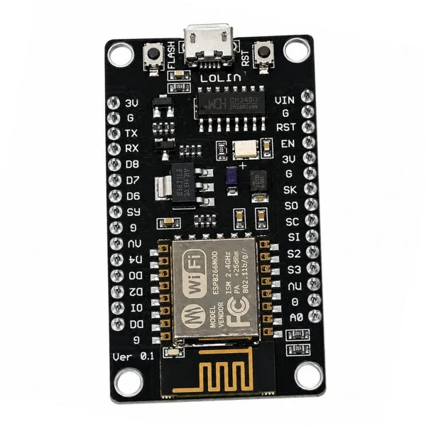
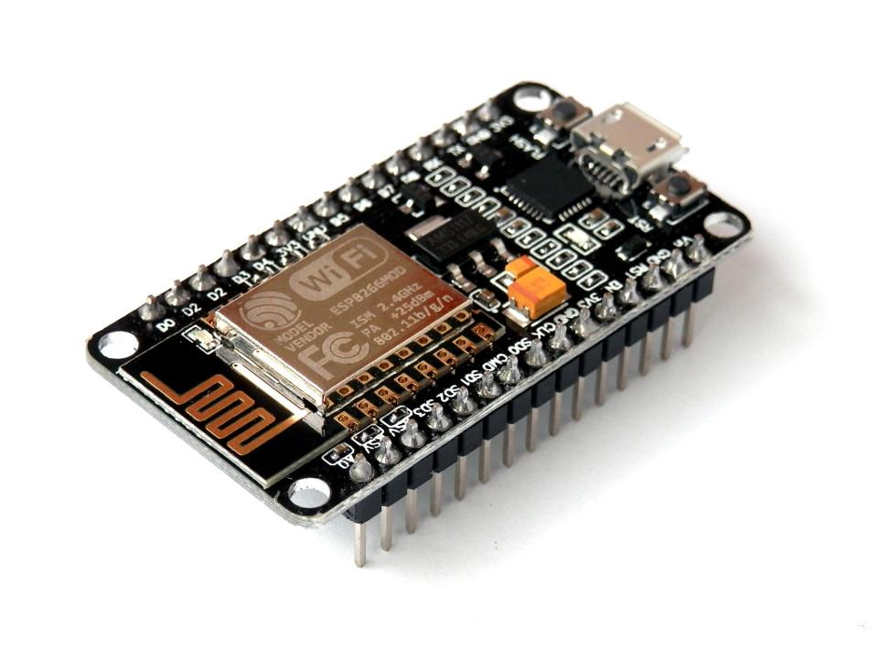
- A NodeMCU board: V2 (CH340) or V3 (CP2102). Price and stock are on the product pages
- A Micro-USB data cable
- A Windows PC with Arduino IDE 2.x
- 2.4 GHz WiFi
- A breadboard, jumper wires, one LED and a 220Ω resistor
Prices can change; check Tekko for the latest.
NodeMCU V2 vs V3
In Tekko's listings the V2 carries a CH340 USB chip and the V3 a CP2102. The ESP8266 on the ESP-12E module is the same in both. So the differences are:
| V2 (CH340) | V3 (CP2102) | |
|---|---|---|
| USB chip | CH340 | CP2102 |
| Windows driver | WCH CH340 driver | Silicon Labs CP210x driver |
| Pins | 30, same layout | 30, same layout |
| Code | identical | identical |
A warning: "V2" and "V3" are not an official standard, and some sellers swap them. Don't trust the name. Read what's printed on the USB chip and pick the driver from that. One more thing: some V3 clones are wider than the V2. A wide board on a breadboard can leave no free holes on one side, which makes jumper wires awkward. Test-fit it, and if needed wire to the pins directly.
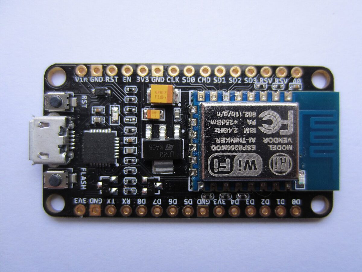
There is also a listing called ESP-12F Node MCU. Same chip family, but the silkscreen may differ, so check what is printed on your board before you wire anything.
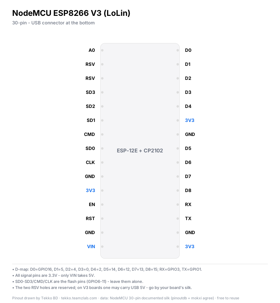
NodeMCU D pins and GPIO numbers
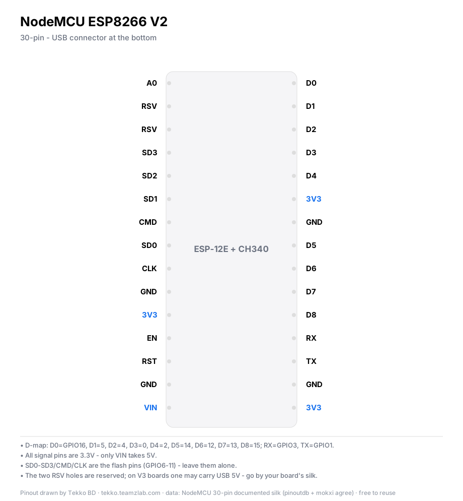
The D0, D1 ... printed on the board are nicknames for ESP8266 GPIO numbers. Pick the NodeMCU board in Arduino IDE and D1, D2 work as names in code. But the moment you copy someone else's sketch with plain numbers, you need this table.
| Printed on board | GPIO | Watch out for |
|---|---|---|
| D0 | 16 | No PWM, interrupts or I2C. Used to wake from deep sleep |
| D1 | 5 | Common I2C SCL |
| D2 | 4 | Common I2C SDA |
| D3 | 0 | Strapping: held low at boot = upload mode |
| D4 | 2 | Strapping: must be high at boot |
| D5 | 14 | SPI CLK |
| D6 | 12 | SPI MISO |
| D7 | 13 | SPI MOSI |
| D8 | 15 | Strapping: must be low at boot |
| RX / TX | 3 / 1 | USB serial. Using them breaks the Serial Monitor |
The flash-memory pins SD0–SD3, CMD and CLK (GPIO 6–11) are off limits.
Safest pins to start with: D1, D2, D5, D6, D7. If something is wired to D3, D4 or D8, the board may refuse to boot.
The single ADC: A0
The ESP8266 has one analog input, A0, and analogRead returns 0 to 1023. On the bare chip that pin tolerates 1.0V at most. NodeMCU boards usually add a resistor divider so A0 can take up to 3.3V. Even so, never go above 3.3V, and never 5V. If you can't confirm your board has the divider, stay under 1V.
Need more than one analog sensor? Add an external ADC module such as the ADS1115, or take an ESP32 instead.
When to pick an ESP32 instead
- You need Bluetooth. The ESP8266 has none
- You need several analog inputs. The ESP32 has many ADC pins
- You are running out of pins. The ESP32 has far more
- You're starting fresh and have no ESP8266 kit in hand: go ESP32. The details are in the ESP32 guide
Pick the NodeMCU when your Smart Home kit or tutorial is written for the ESP8266. Matching the hardware is easier than porting code to the wrong board.
Driver
Plug the board in and open Device Manager → Ports (COM & LPT). A new COM port means the driver is fine. If not, read the USB chip's marking, install the CH340 or CP210x driver, and double-check that the cable carries data.
Add ESP8266 to Arduino IDE
- In File → Preferences, add this to "Additional boards manager URLs":
http://arduino.esp8266.com/stable/package_esp8266com_index.json
- Open Tools → Board → Boards Manager, search
esp8266, and install "esp8266 by ESP8266 Community". - Select Tools → Board → ESP8266 Boards → NodeMCU 1.0 (ESP-12E Module).
- Select the new COM port under Tools → Port.
First sketch: an LED from the browser
This switches the board's own LED from a browser:
#include <ESP8266WiFi.h>
#include <ESP8266WebServer.h>

const char* ssid = "YOUR_WIFI_NAME";
const char* pass = "YOUR_WIFI_PASSWORD";

ESP8266WebServer server(80);

void ledOn()  { digitalWrite(LED_BUILTIN, LOW);  server.send(200, "text/plain", "LED ON"); }
void ledOff() { digitalWrite(LED_BUILTIN, HIGH); server.send(200, "text/plain", "LED OFF"); }

void setup() {
  Serial.begin(115200);
  pinMode(LED_BUILTIN, OUTPUT);
  digitalWrite(LED_BUILTIN, HIGH);
  WiFi.begin(ssid, pass);
  while (WiFi.status() != WL_CONNECTED) {
    delay(500);
    Serial.print(".");
  }
  Serial.println();
  Serial.println(WiFi.localIP());
  server.on("/on", ledOn);
  server.on("/off", ledOff);
  server.begin();
}

void loop() {
  server.handleClient();
}
Upload, open the Serial Monitor at 115200 baud. When the IP appears, open http://<that IP>/on from a phone on the same WiFi.
Note
The built-in LED on a NodeMCU is inverted: LOW turns it on, HIGH turns it off. That is why ledOn() writes LOW. If the light seems backwards, nothing is broken.
Catching the D-pin mix-up
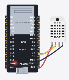
The simulator picture below is an ESP32, because Tekko Sim has an ESP32 and no ESP8266. In it, the DHT22 data wire goes to the pin marked "D4". On the ESP32 that is GPIO 4, and the code says DHT dht(4, DHT22). Put the same wire on a NodeMCU and GPIO 4 is D2, because the NodeMCU's D4 is GPIO 2. This picture is not an ESP8266 circuit; it is here to show the trap.
Verify it works
When the Serial Monitor shows an IP, board, driver and WiFi are all fine. Open /on in a browser and watch the built-in LED. If it lights, everything from WiFi to the web server is working.
Common problems
- Port menu is empty — check the cable carries data, then the driver for your USB chip.
- Upload stops halfway — change the cable, try another USB port on the computer, reset the board and upload again.
- Only dots, never connects — use a 2.4 GHz network, not 5 GHz. SSID and password are case-sensitive.
- Board won't boot after wiring D3, D4 or D8 — those are strapping pins. Unplug the wire, boot, then move it to another pin.
- Garbage in the Serial Monitor — set the baud rate to 115200.
- Fed 5V to A0 — the pin is probably damaged. Remember the limit: 3.3V even with the divider.
FAQ
What is the difference between NodeMCU V2 and V3? In Tekko's listings, V2 has a CH340 USB chip and V3 has a CP2102, so the drivers differ. Pins, chip and code are the same. Some V3 boards are slightly wider and can be awkward on a breadboard.
Which GPIO is D1 on a NodeMCU? GPIO 5. D0=16, D1=5, D2=4, D3=0, D4=2, D5=14, D6=12, D7=13, D8=15. With the NodeMCU board selected in Arduino IDE, writing D1 is enough.
Can I connect a 5V sensor? You can power it from VIN at 5V, but its signal into a pin must stay at 3.3V or below. A raw 5V signal can damage the pin.
Does the ESP8266 have Bluetooth? No. If you need Bluetooth, use an ESP32.
More from Tekko
- Which Arduino board should you buy
- Dev boards category
- Run the ESP32 temperature project free in Tekko Sim
Sources
- Espressif, ESP8266EX Datasheet — espressif.com
- ESP8266 Arduino Core documentation (installing, GPIO and pin reference, WiFi) — arduino-esp8266.readthedocs.io
Try it free before you buy
This project runs free in Tekko Sim, right in your browser — before you spend a taka.
ESP32: send temperature to the cloud — Run in Sim