Line Follower Robot: Sensors, Motors and Code
Build a line follower robot: 2 IR sensors or a 5-channel array, L298N and 18650 wiring, a P-control sketch line by line, tuning, and a practice track.
You signed up for the robotics club event, you have a week, and everyone says "just build a line follower". Fair: it is the standard first robot. A line follower robot drives itself along a black line on the floor. Sensors pointing down see the line, the Arduino decides how fast each wheel should turn, and an L298N motor driver does the turning.
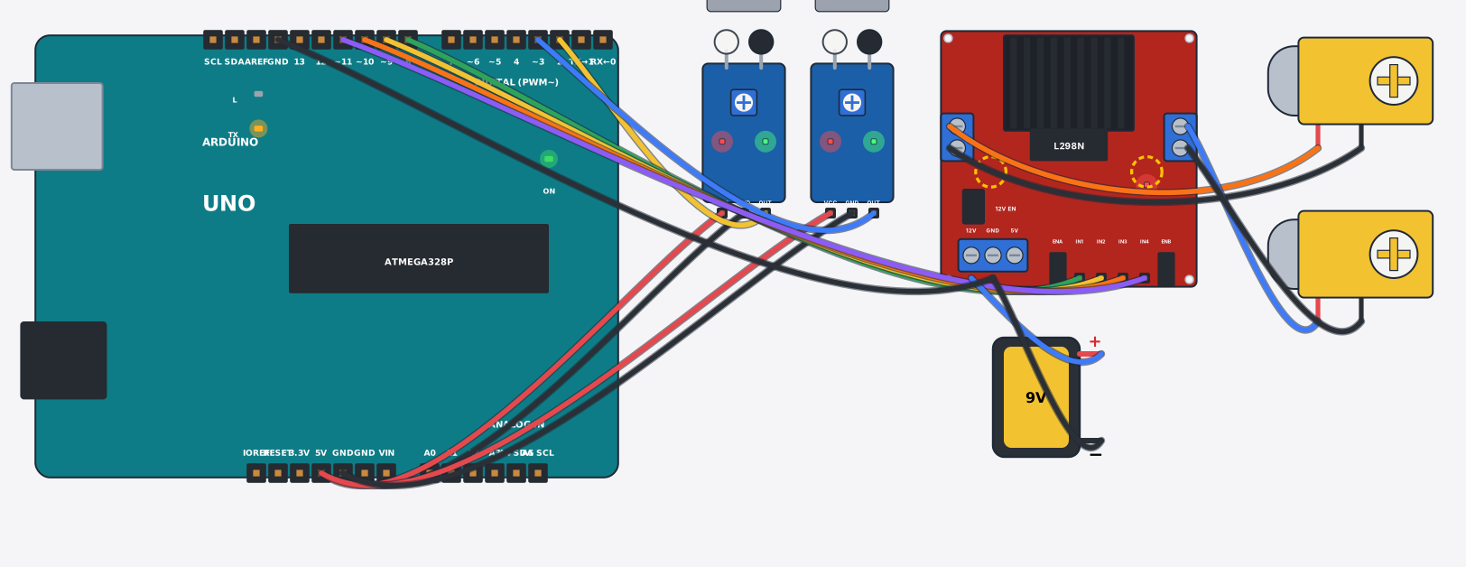
This guide covers the whole build: which sensor to pick, what the battery gives you, where each wire goes, a P-control sketch explained line by line, tuning, and a practice track. If you only want the circuit and the simple code, run the free simulator from the link under the first figure below. Seeing it work first makes the rest easier to follow.
What you need
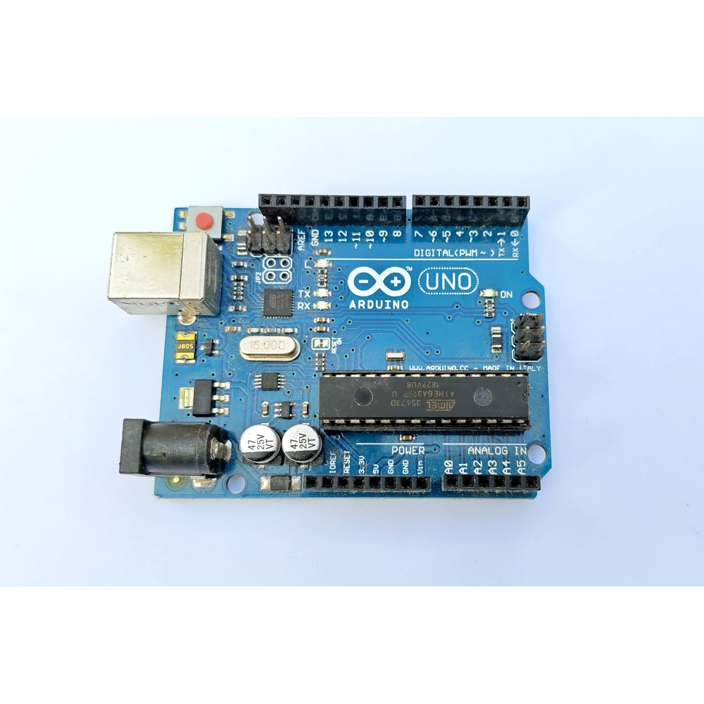
- Arduino Uno R3
- Sensors: 2 IR sensor modules (simple version) or a 5-channel line array sensor (competition version)
- L298N motor driver module
- A 2WD robot chassis kit, or two gear motors + two wheels + one caster wheel separately
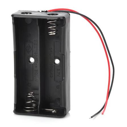
- Two 18650 cells and a 2S battery holder
- A slide switch and jumper wires
- Black insulation tape, and a big matte white surface for the track
If you would rather not collect every part yourself, the cards below include the line follower kits too. Check the shop page for each.
Prices can change; check Tekko for the latest.
How a line follower robot works
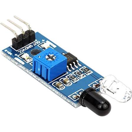
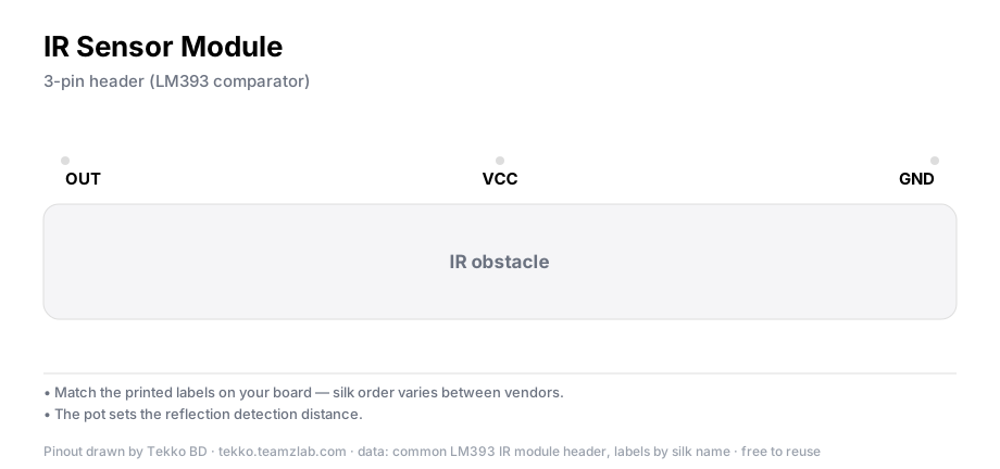
An IR sensor module has an IR LED that sends light down and a receiver that measures what comes back. White floor reflects it. A black line swallows it. On an FC-51 style module OUT is LOW over white and HIGH over black. Yours may be the other way round, so watch the little LED on the module and note when it lights.
With two sensors, the line runs between them. The logic fits in four rows:
| Left sensor | Right sensor | Robot does |
|---|---|---|
| white | white | go straight (both wheels on) |
| black | white | turn left (left wheel off) |
| white | black | turn right (right wheel off) |
| black | black | stop |
It works. The catch is that each wheel is either on or off, nothing in between. The robot jerks along, and once you raise the speed it shoots off the line. The fix is proportional control (P-control): measure how far off the line you are, and steer by that amount. Far off, turn hard. Slightly off, turn gently. That needs more sensors, which is where the 5-channel array comes in.
Which sensor: 2 IR modules or a 5-channel array
| 2 IR modules | 5-channel array | |
|---|---|---|
| Arduino pins | 2 digital | 5 digital |
| Steering | on / off | smooth, by how far off |
| Knows how far off the line | no, only "off" | roughly, in 5 steps |
| Code | short and simple | longer, but P-control works |
| School project | fine | overkill |
| Competition | loses once speed goes up | start here |
My pick: for a school project or a first robot, start with 2 IR sensors, run it in the simulator, then build it. If you are entering a competition, take the array from day one. Building with 2 IR and swapping later means redoing the code and the sensor mount. The array has its downsides: more pins, a little more fuss getting clean black-and-white readings, and the board has to sit square over the line.
Specification
| Item | Value |
|---|---|
| L298N motor supply | 5–35V, 2A max per channel |
| L298N voltage drop | about 2V (motors get less than the battery) |
| 2S 18650 pack | 7.4V nominal, 8.4V full |
| Arduino Uno VIN | 7–12V recommended |
analogWrite() | 0–255, PWM pins 3, 5, 6, 9, 10, 11 on the Uno |
| Yellow TT gear motor | usually 3–6V, check the label on yours |
From a 7.4V pack (8.4V full) the L298N drops about 2V, so the motors see roughly 5.4–6.4V. That suits a yellow TT motor without a separate regulator. The 9V battery in the simulator is there for the demo. On a real robot a 9V battery cannot supply the motor current.
Charging and handling 18650 cells is its own topic. Read the 18650 battery and BMS safe-use guide before you charge anything.
Chassis and sensor placement
Mount the two motors on the chassis, with a caster wheel at the front or back. Put the sensors at the front, as far ahead of the wheel axle as you can. The further forward they sit, the earlier the robot sees itself drifting.
- 2 IR: set the gap between them slightly wider than the line. With the line centred, both read white.
- 5-channel array: centre sensor on the robot's centreline, and the whole array wider than the line.
- Height: as low as you can without scraping, near 1 cm. Higher up, the white/black difference gets blurry.
IR modules have a small potentiometer. Hold the module over white floor and turn it until you find the point where the LED changes state, then check it flips the other way over black tape.
Wiring
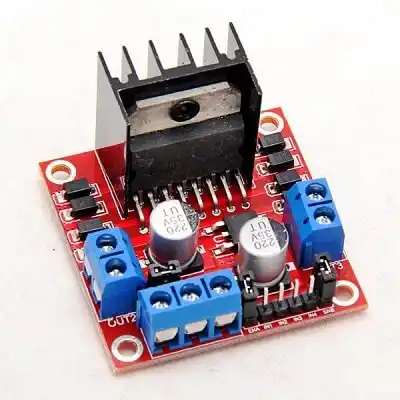
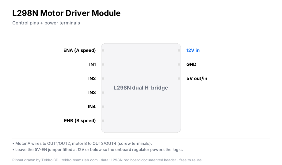
Power: battery + goes to the slide switch, and from the switch to the L298N 12V terminal and the Arduino VIN. Battery − goes to the L298N GND and the Arduino GND, so every ground is common. Leave the L298N 5V jumper in place, and do not connect its 5V pin to the Arduino.
Two-IR version (as in the figure): VCC → 5V, GND → GND, left OUT → D2, right OUT → D3. L298N: IN1 → D8, IN2 → D9, IN3 → D10, IN4 → D11. Left motor on OUT1/OUT2, right motor on OUT3/OUT4. Leave the two EN jumpers on, so the motors always run at full speed.
5-channel version needs variable speed, so remove the ENA and ENB jumpers:
| L298N | Arduino |
|---|---|
| IN1 / IN2 | D8 / D9 (left motor) |
| IN3 / IN4 | D10 / D11 (right motor) |
| ENA | D5 (PWM) |
| ENB | D6 (PWM) |
Array VCC → 5V, GND → GND, the five outputs left to right → A0, A1, A2, A3, A4. If your board labels the pins differently, match them by label.
Note
If a motor spins the wrong way, do not touch the code. Swap that motor's two wires at the L298N.
Run it with 2 IR first
The two-IR code is the table above in code: read both sensors with digitalRead, stop the wheel on the side that sees black, keep the other wheel on. The full code, and a way to flip each sensor on and off, is behind the simulator link under the first figure. Running it on the real robot proves the wiring, motor directions and sensor polarity all work. Then move on to P-control.
P-control sketch for the 5-channel array
const int sensorPin[5] = {A0, A1, A2, A3, A4};   // left to right
const int weight[5]    = {-2, -1, 0, 1, 2};
const int IN1 = 8, IN2 = 9, IN3 = 10, IN4 = 11;
const int ENA = 5, ENB = 6;

const int BASE  = 140;   // straight-line speed, 0-255
const int KP    = 40;    // how hard it turns
const int BLACK = HIGH;  // write LOW if your array gives LOW on black

float lastError = 0;

void drive(int left, int right) {
  left  = constrain(left,  -255, 255);
  right = constrain(right, -255, 255);
  digitalWrite(IN1, left  >= 0 ? HIGH : LOW);
  digitalWrite(IN2, left  >= 0 ? LOW  : HIGH);
  digitalWrite(IN3, right >= 0 ? HIGH : LOW);
  digitalWrite(IN4, right >= 0 ? LOW  : HIGH);
  analogWrite(ENA, abs(left));
  analogWrite(ENB, abs(right));
}

void setup() {
  for (int i = 0; i < 5; i++) pinMode(sensorPin[i], INPUT);
  pinMode(IN1, OUTPUT); pinMode(IN2, OUTPUT);
  pinMode(IN3, OUTPUT); pinMode(IN4, OUTPUT);
  pinMode(ENA, OUTPUT); pinMode(ENB, OUTPUT);
}

void loop() {
  int sum = 0, count = 0;
  for (int i = 0; i < 5; i++) {
    if (digitalRead(sensorPin[i]) == BLACK) {
      sum += weight[i];
      count++;
    }
  }

  if (count == 0) {                    // line lost
    if (lastError > 0) drive(BASE, -BASE);   // was on the right, spin right to find it
    else               drive(-BASE, BASE);
    return;
  }

  float error = (float)sum / count;    // -2 (line on the left) to +2 (right)
  lastError = error;

  int turn = KP * error;
  drive(BASE + turn, BASE - turn);
}
Line by line:
weight[]: the five sensors get the numbers -2, -1, 0, 1, 2 from left to right. Line on the left gives a negative number, on the right a positive one.BASE: the straight-line speed of both wheels. Keep it low at first and raise it once the robot follows properly.KP: the one number P-control is about. Higher means a harder turn for the same drift.drive(): a negative speed means that wheel runs backwards, so the IN pins and the EN PWM are set separately.constrainkeeps the speed inside 0–255.- First part of
loop(): add up the numbers of the sensors that see black, and count how many see it. count == 0: no sensor sees the line. The robot spins on the spot toward the side where the line was last seen. Without this, a robot that loses the line just drives away.error: the average of the black sensors' numbers. Only the middle sensor on black gives 0, only the far-left sensor gives -2.turn:KP * error. If the line drifts right,erroris positive, so the left wheel speeds up and the right slows, and the robot turns right to get back on it.
When every sensor sees black at once (a crossing, or a stop box), error comes out as 0 and the robot goes straight on. What it should do there depends on the competition rules, so code that case yourself.
Tuning
- Wheels in the air first. Rest the robot on a book so the wheels spin freely. Slide black tape left and right under the sensors and watch which wheel slows. Tape to the right should slow the right wheel.
- Start slow.
BASEaround 100,KPat 20. When it follows the line, raiseKPin steps of 10. - Too much `KP`: the robot wobbles side to side even on a straight line. Too little: it runs wide on curves and leaves the line. Find the middle.
- Then raise
BASE, and recheckKPeach time, because the right number changes with speed.
If the wobble will not go away, the next tool is a D term: add how much error changed since the last loop to turn (this is the "D" in PID). Get P working first.
Building a practice track
A home track is easy:
- Line: black insulation tape. Shop tape is usually around 2 cm wide, but measure yours; your sensor spacing depends on it.
- Surface: matte white. Glossy floor tiles reflect light and confuse the sensors. White flex banner or a white board works.
- Shape: straight first, then gentle curves, then a 90-degree corner. Corners are where robots lose the line most.
- Light: direct sunlight from a window disturbs IR sensors. Try the robot under room light and in the sun.
For a real event, the track size, line colour, maximum robot size and number of motors are in the organiser's rulebook. Read it first. Their numbers win over your tape.
Verify it works
Power on and set the robot on a white patch, then on the line. It should follow straight parts, take curves smoothly, and come back to the line if you nudge it off by hand.
Common problems
- Robot drives away from the line — sensor polarity is flipped (change the
BLACKvalue), or a motor is wired backwards. With the wheels lifted, calldrive(150, 150)and check both wheels go forward. - One wheel runs backwards — swap that motor's two wires at the L298N OUT terminals.
- Wobbles on a straight line —
KPorBASEtoo high. Lower both a little. - Leaves the line on curves — too fast and
KPtoo low. LowerBASE, then raiseKP. - Fine indoors, confused in sunlight or on glossy floor — ambient light is disturbing the IR sensors. Put a small black paper hood over the sensors and use a matte surface.
- Arduino resets the moment the motors start — battery voltage is sagging, or a switch or wire joint is loose. Check the cells are fully charged and tighten the joints.
- LEDs on, robot does not move — you removed the ENA/ENB jumpers but did not wire D5 and D6, or
BASEis so low the motors cannot turn. Check the wires and raiseBASE.
FAQ
Can two IR sensors alone win a competition? They handle straight and gentle-curve tracks. Wide curves, 90-degree corners and high speed show their limit. Find out what the track looks like from the organiser's rulebook first.
Will an Arduino Nano work instead of the Uno? Yes. Keep the same pin numbers, just make sure ENA and ENB sit on PWM pins 5 and 6.
Which motor RPM, 100 or 200? For a first robot a slower motor is easier to control, and following the line gets harder as speed goes up. Get it right slow, then move to the faster motor.
Do I really need PID? No. Get P working first. Add a D term only if the wobble stays.
Your next build
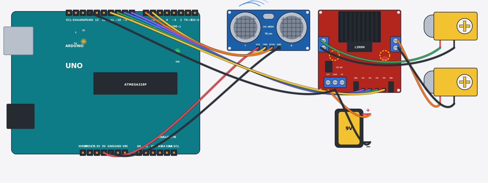
Once the line follower runs, an obstacle avoiding robot is the natural next step. Same L298N and chassis, with an HC-SR04 ultrasonic sensor instead. It stops when a wall is about 20 cm away, then backs up and turns.
More from Tekko
- Robotics category: chassis, motors, wheels, motor drivers
- Sensors category: IR and line array sensors, and more
- Not sure which board to pick? Which Arduino board to buy
Sources
- L298 Dual Full-Bridge Driver datasheet — st.com
- Arduino
analogWrite()reference — arduino.cc - Arduino Uno Rev3 power and PWM pins — docs.arduino.cc
Try it free before you buy
This project runs free in Tekko Sim, right in your browser — before you spend a taka.
Line Follower Robot using Arduino — Run in Sim