Relay Module Guide: Pins, Active-LOW, Arduino, ESP32
Relay module pins (VCC, IN, COM, NO, NC), why HIGH leaves the relay off, wiring to Arduino and ESP32, 1/2/4-channel vs SSR, and where 220V stops.
An Arduino pin should not source more than about 20 mA. A small water pump pulls close to an amp. Something has to sit between them: a switch that the Arduino can flip with a weak signal but that carries the big current itself. That switch is a relay module, the blue cube that clicks.
Simple enough, until the first thing everybody hits: you write HIGH, and the relay does nothing. This guide covers why, the pins, 1/2/4-channel boards versus an SSR, the ESP32 trap, and one hard line: household 220V stays out of every project here.
What you need
- A relay module (1, 2 or 4 channel; start with 1)
- An Arduino Uno or an ESP32
- Jumper wires
- A small low-voltage load: a 12V LED strip, fan or pump, with its own battery or adapter
- A 1N4007 diode if the load is a motor or pump
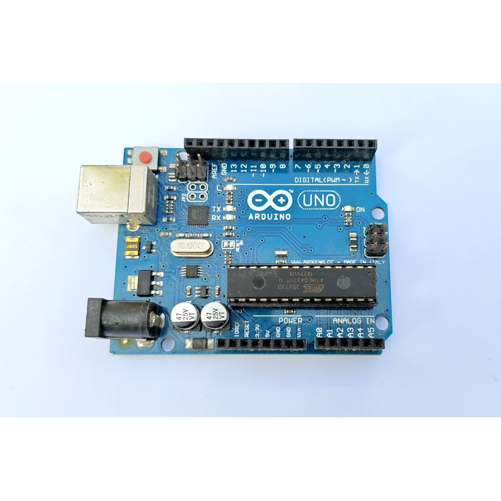
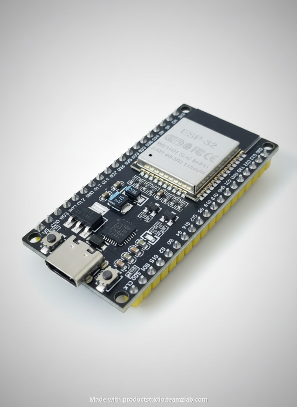
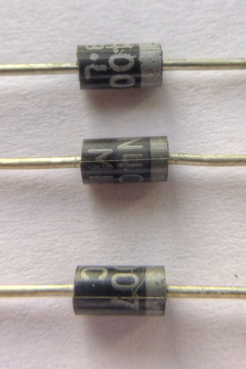
Prices can change; check Tekko for the latest.
What a relay actually does
Inside is a coil. Current through the coil makes a magnet, the magnet pulls a metal blade, and the blade swings from one contact to another. That is the click.
The coil circuit and the contact circuit are not connected to each other. One side is your Arduino and 5V; the other side is the load and its own power. If you let those two sides touch, you have wasted the relay.
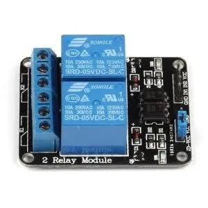
The blue cube relays on most modules are SRD-05VDC-SL-C types. That datasheet gives a 5V DC coil at 0.36 W, so about 70 mA while on, and contacts rated 10A at 250V AC or 10A at 30V DC. Read the print on your own relay and match it.
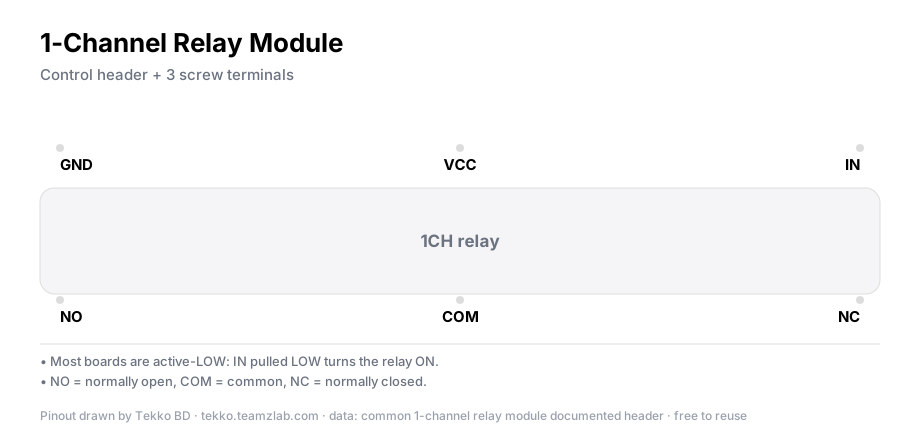
Pins: two sides, two jobs
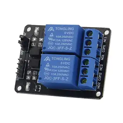
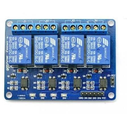
| Pin | Side | Job |
|---|---|---|
| VCC | control | 5V for the coil |
| GND | control | ground |
| IN | control | signal from the Arduino |
| COM | load | common: one end of the load wire goes here |
| NO | load | Normally Open: open when the relay is off, closed when it is on |
| NC | load | Normally Closed: closed when the relay is off, open when it is on |
To turn a load on, use COM and NO. Wire through NC and the load runs the moment power appears, including during a reset. Nobody wants a pump that starts itself while the board reboots.
One warning: the order of GND, IN and VCC is not the same on every board. Trust the print on your board, not a picture.
HIGH leaves it off: the active-LOW trap
Most relay modules are active-LOW. LOW (0V) on IN switches the relay on; HIGH switches it off. The reason is in the board design: pulling IN toward GND lets current flow through the transistor or optocoupler input.
So you write digitalWrite(7, HIGH) and nothing happens. Or worse: the Arduino starts up, the pin defaults LOW, the relay clicks on by itself, and so does the pump.
Some boards have a jumper to choose the trigger level. If yours does not, handle it in code. Naming the two states stops most mistakes:
const int RELAY = 7;
const int RELAY_ON  = LOW;    // active-LOW board
const int RELAY_OFF = HIGH;

void setup() {
  digitalWrite(RELAY, RELAY_OFF);  // write the off level first...
  pinMode(RELAY, OUTPUT);          // ...then make it an output: no click at boot
}

void loop() {
  digitalWrite(RELAY, RELAY_ON);
  delay(2000);
  digitalWrite(RELAY, RELAY_OFF);
  delay(2000);
}
Mind the order in setup(). Writing HIGH while the pin is still an input turns on the internal pull-up, so when you switch to output the pin lands on HIGH. Do it the other way round and the pin sits LOW for a moment, long enough for one click.
Not sure which kind you have? One-line test: with no load connected, touch IN to GND. If it clicks, it is active-LOW.
1, 2, 4 channels, or an SSR
| Type | Pick it when | Catch |
|---|---|---|
| 1 channel | first project, one load | simplest; most tutorials assume it |
| 2 channel | two loads, or reversing a motor | give it its own 5V once the load grows |
| 4 channel | home automation, four loads | four coils on at once draw about 280 mA, a lot for the Arduino 5V rail |
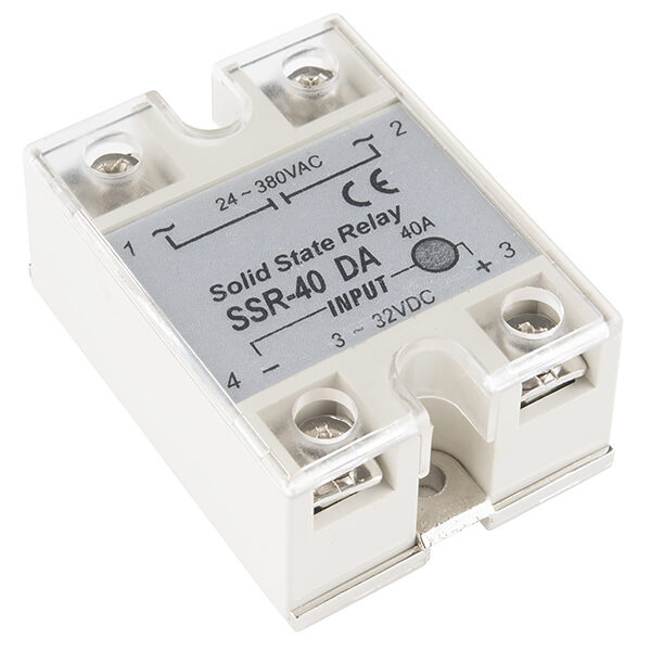
| SSR (e.g. SSR-40DA) | frequent switching, silence | AC loads only, not DC |
What would I buy? One channel to begin with. For two or three loads, a 4-channel board with its own 5V supply, because four coils on at once eat a large part of the 500 mA a USB port can give.
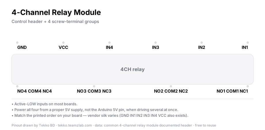
An SSR has no moving parts: no click, no contact wear, and you can switch it often, which is why heaters and dimmers use it. You pay for that in two ways. The SSR-40DA switches AC loads only (3-32V DC in, AC out), and when off it still leaks a tiny current, so some LED bulbs glow faintly even when "off". For a small DC project you will not need one.
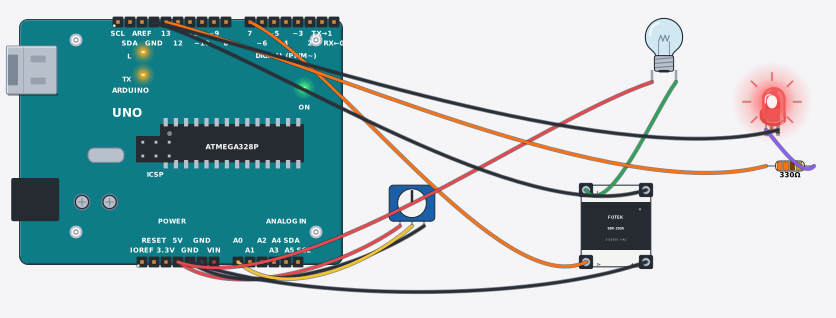
In Tekko Sim, the ssr-heater project shows an SSR splitting a 2-second cycle between on and off to hit a chosen heat percentage. It is a simulation; nothing real is heating.
Wiring to an Arduino
The code above uses pin 7.
- Relay VCC to Arduino 5V
- Relay GND to Arduino GND
- Relay IN to pin 7
- One wire of the load to relay COM
- Relay NO to the + of the load's power (12V battery or adapter)
- Other wire of the load to the - of the load's power
The load's current flows through the relay contacts. The Arduino's 5V and the load's 12V never meet on one wire.
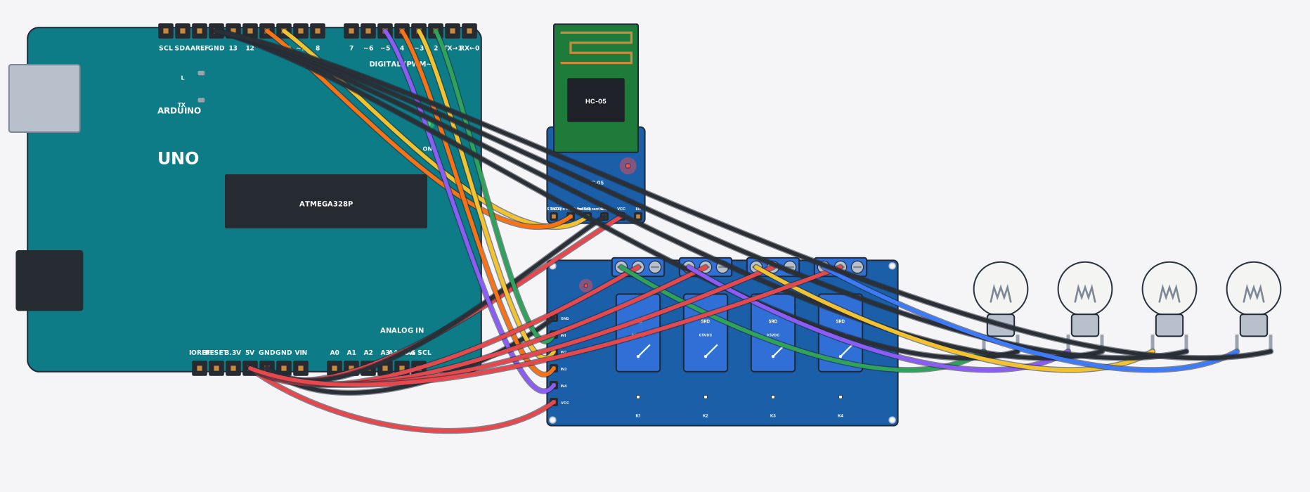
Tekko Sim's home-automation project switches four lamps through a 4-channel relay over Bluetooth, and its code follows the same active-LOW rule. Practice there before you buy.
Driving it from an ESP32: the 3.3V problem
ESP32 GPIO outputs are 3.3V, while most relay modules want 5V on VCC. Give the coil its 5V (from the board's VIN or USB 5V pin) and accept that the signal on IN is 3.3V logic.
Two traps live here:
- On an active-LOW board, HIGH may not fully switch the relay off. With VCC at 5V and IN at 3.3V there is still a 1.7V gap, and the input LED or optocoupler can stay faintly on. The symptom is a relay that will not release, or half-clicks.
- Some GPIOs wobble during boot. GPIO 0, 2, 12 and 15 are strapping pins; a relay on them may twitch at startup. Use 26, 27 or 32 instead.
The fix is to look for a JD-VCC jumper on the board. If there is one, pull it, feed JD-VCC with 5V and VCC with 3.3V, and the logic side really runs at 3.3V. If there is no such jumper, buy a board that says it supports a 3.3V trigger.
The code is identical on ESP32, with RELAY = 26. Check Espressif's datasheet for the pin current limit, and never power the coil straight from a pin; the module's IN pin is all you need.
Inside the board: optocoupler and flyback
A good module has a small diode across the coil. When the coil switches off it kicks a reverse voltage spike (flyback), and the diode absorbs it so the driver transistor survives. Many boards add an optocoupler too, which separates the Arduino side from the coil side with light.
Here is what people mix up: the module's diode protects the coil driver, not your load. A 12V motor or pump kicks back as well when it stops, and that spike lands on the relay contacts as sparks. Put a diode across the motor's two wires (a 1N4007, stripe toward +). Which diode and why is in the 1N4007 vs 1N4148 guide.
Where 220V stops
The contact rating says 250V AC, so people think: fine, I'll switch the room light. No. The rating is real, but the problem is your wiring: exposed screw terminals, a breadboard near a mains line, a house earth you have not checked. Every project in this guide is a DC load under 12V.
Warning
Relay modules: in beginner projects switch only low-voltage loads — a 12 V motor, lamp, fan or pump. Never wire household 220 V mains into a relay circuit; a mains mistake means dangerous shock and fire, and no breadboard project makes that safe. Mains work is for experienced adults, done to code. Keep the two sides apart: the input side takes the board's 5 V and a signal pin, the load side takes your battery or adapter — never mix them. For inductive loads like motors and pumps, check the flyback diode or the module's built-in protection is in place. Unplug the load wiring when finished, and let the relay cool before touching it.
That is also why the SSR-40DA needs care: its output terminals are made for the AC line. Whoever wires a heater or a pump to mains does it as a qualified electrician.
Verify it works
Test with no load first. Upload the code and the relay should click once every 2 seconds while the little LED on the board toggles. Only after that, connect the load to COM and NO.
Common problems
- The relay never clicks. Check VCC and GND. Then touch IN to GND: if it clicks, the board is fine and the problem is your code or pin.
- HIGH is off, LOW is on. The board is active-LOW. Use
RELAY_ONandRELAY_OFFconstants. - The relay clicks on at boot. In
setup(), write the off level first, then callpinMode(..., OUTPUT). - It chatters on and off. The 5V is sagging and the coil is not getting full current. Use a separate 5V supply and join all grounds.
- The Arduino resets when the motor runs. Flyback spike. Fit a diode across the motor and do not power the motor from the Arduino 5V.
- The load is always on. You wired it to NC instead of NO.
- The relay died from frequent switching. The datasheet gives about 10 million mechanical operations but only around 100,000 electrical ones under load. If you need several switches a minute, think SSR.
FAQ
Relay module or SSR? A normal relay for DC loads and learning projects. An SSR for frequent switching and AC heaters, but AC work belongs to a qualified person.
Can an ESP32 drive a relay module? Often yes, and plenty of boards work fine. The 3.3V trap above is real though, so test your board before you build around it.
How many loads per channel? One channel switches one load. Two loads that always switch together can share one channel, as long as their total current stays inside the contact rating.
Will four relays run from the Arduino 5V pin? Possible, but risky. Four coils on at once are about 280 mA, on top of the board LEDs and any sensors. Give them their own 5V.
More from Tekko
- Modules category: 1, 2 and 4 channel relays, plus the SSR
- Dev boards: Uno and ESP32
- Run it free first: home automation in Tekko Sim
- A full project built around a relay: automatic plant watering
- Before switching things from sensor readings, understand the sensor: DHT11 sensor guide
Sources
- SRD-05VDC-SL-C relay datasheet (Songle): 5V coil, 0.36 W, contact ratings, life
- Arduino digital pins documentation, arduino.cc: pin current limits
- ESP32 datasheet, espressif.com: GPIO and strapping pins
Try it free before you buy
This project runs free in Tekko Sim, right in your browser — before you spend a taka.
Home Automation using Arduino: 4 Lamps over Bluetooth & Relays — Run in Sim