ESP32 Guide: Which Board, Pin Traps, Arduino IDE Setup
ESP32 DevKit vs C3 SuperMini vs NodeMCU vs Uno, the pin traps (GPIO 34–39, ADC2, strapping), Windows drivers, and a first WiFi sketch that works.
Say you want to switch on a light from your phone for the science fair. You sit down with an Arduino Uno and find out the Uno has no WiFi. The board swap eats three days. One question up front saves them: does the project need the internet, or a phone?
If yes, you want an ESP32. One small board with a dual-core processor, WiFi and Bluetooth built in, programmed from the same Arduino IDE you already know. This guide compares four boards, lists the pin mistakes everyone makes once, walks through the Windows setup, and ends with a first sketch.
What you need
- An ESP32 DevKit (30 pins, Type-C port). Price and stock are on the product page
- A USB Type-C data cable. A charge-only cable powers the board but never shows a port on the computer
- A Windows PC with Arduino IDE 2.x
- A 2.4 GHz WiFi network. A phone hotspot works
- A breadboard, jumper wires, one LED and a 220Ω resistor
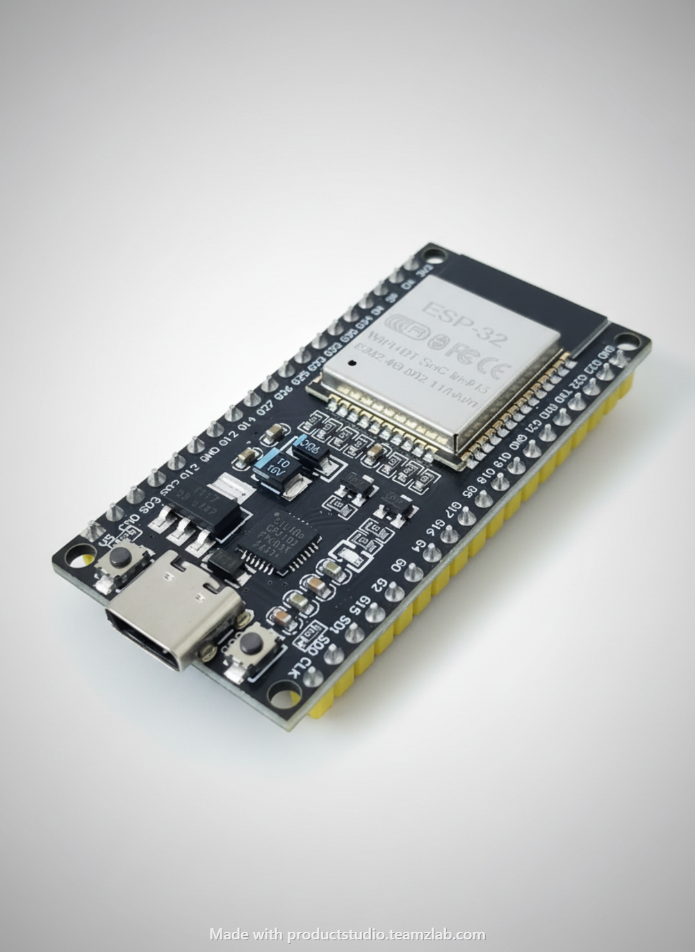
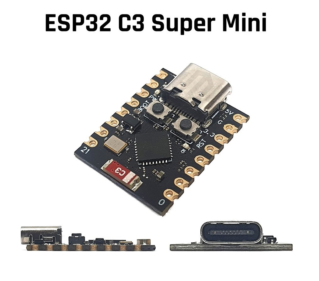
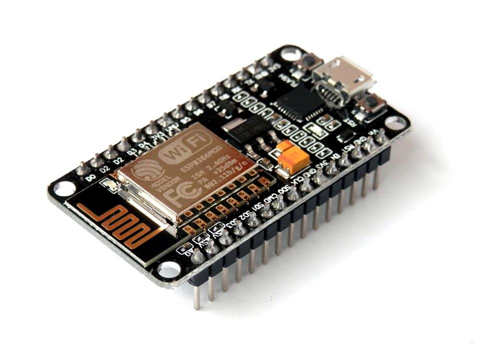
Prices can change; check Tekko for the latest.
ESP32 vs the other boards
| ESP32 DevKit | ESP32-C3 SuperMini | NodeMCU (ESP8266) | Arduino Uno R3 | |
|---|---|---|---|---|
| Processor | Xtensa LX6, 2 cores, up to 240 MHz | RISC-V, 1 core, up to 160 MHz | Tensilica L106, 1 core, 80 MHz | ATmega328P, 16 MHz |
| WiFi | 2.4 GHz b/g/n | 2.4 GHz b/g/n | 2.4 GHz b/g/n | none |
| Bluetooth | Classic + BLE | BLE 5 | none | none |
| Logic voltage | 3.3V | 3.3V | 3.3V | 5V |
| ADC | 12-bit | 12-bit | 10-bit, one pin only | 10-bit, 6 pins |
| Pick it when | most IoT projects | tiny enclosure, battery, BLE | older ESP8266 kits and tutorials | learning without WiFi |
Our pick is the ESP32 DevKit. More pins, more memory, and the most example code online. The one real downside is 3.3V logic, so 5V sensors can't go straight onto a pin. More on that below.
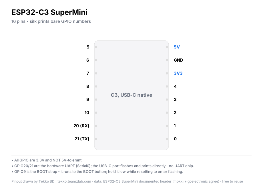
The ESP32-C3 SuperMini is much smaller: 16 pins, and the USB-C port uploads directly. Good for a build that has to fit a small box. One core and fewer pins means you can run out quickly once a display and two sensors are attached.
NodeMCU is the ESP8266: an older chip, no Bluetooth. Buy it only if your kit or tutorial is written for it, such as the Smart Home kit. It has its own guide.
No WiFi needed? Stay with the Uno. Don't take on 3.3V headaches just to learn blinking.
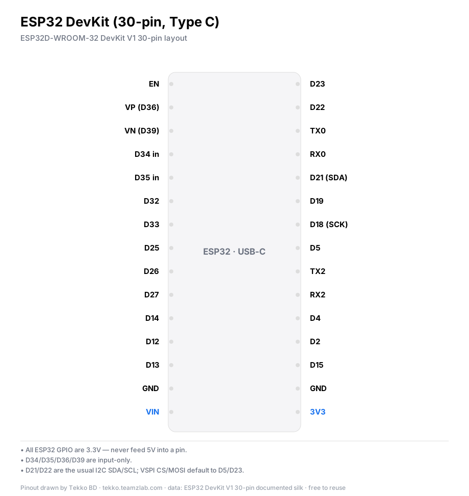
Five ESP32 pin traps
1. Every pin is 3.3V. The Echo pin of an HC-SR04 and the outputs of many old Arduino modules swing to 5V. Feed that straight into an ESP32 pin and you can kill the pin. Put a voltage divider or a level shifter in between.
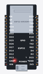
2. GPIO 34, 35, 36 and 39 are input-only. You can't drive an LED from them, and they have no internal pull-up or pull-down. A button on these pins needs an external resistor.
3. Strapping pins: GPIO 0, 2, 5, 12 and 15. At power-up the ESP32 reads their levels to decide how to boot. GPIO 0 held low puts the board into upload mode. A module that holds GPIO 12 high during power-up can stop the board booting at all. If a board that worked yesterday won't boot today, unplug whatever you added on these pins first.
4. With WiFi on, don't trust `analogRead` on ADC2 pins. ADC2 covers GPIO 0, 2, 4, 12–15 and 25–27. Put analog sensors on ADC1, which means GPIO 32–39. The ESP32 ADC is also not perfectly linear; readings near both ends of the range are a little off.
5. Leave GPIO 6–11 alone. They are wired to the board's flash memory. The DevKit doesn't even bring them out to the header, but if another board does, don't touch them.
USB driver
Plug the board in and open Device Manager → Ports (COM & LPT). A new COM port means the driver is fine, so skip ahead.
If nothing appears, find the small USB chip on the board. CP2102 needs the Silicon Labs CP210x driver, CH340 needs the WCH CH340 driver. Download either from the manufacturer's site. The ESP32-C3 SuperMini has no separate USB chip; USB is inside the C3 itself. If no port shows up, hold the BOOT button while plugging it in.
Add ESP32 to Arduino IDE
- Open File → Preferences. In "Additional boards manager URLs" paste:
https://espressif.github.io/arduino-esp32/package_esp32_index.json
- Open Tools → Board → Boards Manager, search
esp32, and install "esp32 by Espressif Systems". It is a large download, so start it on a good connection. - Choose Tools → Board → esp32 → ESP32 Dev Module. For the C3, choose "ESP32C3 Dev Module" and set USB CDC On Boot: Enabled under Tools, or the Serial Monitor stays empty.
- Pick the new COM port under Tools → Port.
First sketch: join your WiFi
#include <WiFi.h>

const char* ssid = "YOUR_WIFI_NAME";
const char* pass = "YOUR_WIFI_PASSWORD";

void setup() {
  Serial.begin(115200);
  WiFi.begin(ssid, pass);
  while (WiFi.status() != WL_CONNECTED) {
    delay(500);
    Serial.print(".");
  }
  Serial.println();
  Serial.print("IP: ");
  Serial.println(WiFi.localIP());
}

void loop() {}
Upload, open the Serial Monitor and set the baud rate to 115200. A few dots, then an IP address, means the board is on your WiFi.
Note
The ESP32 only sees 2.4 GHz WiFi. If your router is 5 GHz only, or the two bands share a name and the router pushes you to 5 GHz, the dots will go on forever. SSID and password are case-sensitive.
The projects people actually build
- Switch a light from your phone. The phone sends an MQTT message ("ON" or "OFF"), the ESP32 hears it and drives a pin HIGH or LOW. In the sim project below, GPIO 2 switches exactly like this.
- Send room temperature to the cloud. A DHT22 sensor and an HTTP request. Read the DHT11 guide first; the DHT22 uses the same library.
- Motion alert. A PIR sensor sees movement, a buzzer sounds at home, and a message goes to the cloud.
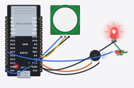
Load-shedding adds one thing to plan for: when the router goes off, the ESP32 drops WiFi, and unless your sketch handles it, it never comes back. Put this at the top of loop():
void loop() {
  if (WiFi.status() != WL_CONNECTED) {
    WiFi.reconnect();
    delay(5000);
  }
  // your actual work here
}
Warning
relay modules: in beginner projects switch only low-voltage loads — a 12 V motor, lamp, fan or pump. Never wire household 220 V mains into a relay circuit; a mains mistake means dangerous shock and fire, and no breadboard project makes that safe. Mains work is for experienced adults, done to code. Keep the two sides apart: the input side takes the board's 5 V and a signal pin, the load side takes your battery or adapter — never mix them. For inductive loads like motors and pumps, check the flyback diode or the module's built-in protection is in place. Unplug the load wiring when finished, and let the relay cool before touching it.
If you'd rather start from a bundle, there is the ESP32 IoT Starter Kit, so you aren't hunting for sensors one by one.
Verify it works
When the Serial Monitor prints an IP address, three things are working together: board, driver and WiFi. Ping that IP from a phone on the same network to confirm the board answers.
Common problems
- Upload sticks on `Connecting........` — hold the board's BOOT button when the upload starts and release it once "Writing" appears. Still stuck? Change the cable; many are charge-only.
- No port in the Port menu — check the cable is a data cable, then the driver in Step 1.
- Garbage characters in the Serial Monitor — set the baud rate to 115200.
- `Brownout detector was triggered` and endless restarts — the supply voltage is sagging. The ESP32 pulls a burst of current when WiFi starts. Plug straight into a computer port instead of a hub, or use a shorter, thicker cable.
- `analogRead` is wrong only when WiFi is on — the pin is on ADC2. Move the sensor to ADC1 (GPIO 32–39).
- A board that worked now won't boot — remove whatever you just wired to GPIO 0, 2, 12 or 15.
FAQ
What is the difference between ESP32 and NodeMCU? NodeMCU is built on the ESP8266 chip. The ESP32 has two cores, Bluetooth and more pins. Both are 3.3V and both program from Arduino IDE, but each needs its own board package.
Does Arduino code run on an ESP32? Most simple code does: digitalWrite, Serial, delay. The differences show up in pin names, the ADC, and some libraries. The Servo library, for one, needs the ESP32 version.
Can a 5V sensor ever work with it? Yes, if the signal is brought down to 3.3V before it reaches the pin. You can still power the sensor from 5V (the board's VIN pin). The limit applies to signal pins only.
Can an ESP32 drive a relay? Yes, but some relay modules don't trigger reliably from a 3.3V signal. The relay guide covers how to pick one.
More from Tekko
- NodeMCU ESP8266 guide — what changes if you buy an ESP8266 board
- Which Arduino board should you buy — for projects without WiFi
- Dev boards category
- Run the ESP32 MQTT project free in Tekko Sim before you buy anything
Sources
- Espressif, ESP32 Series Datasheet — espressif.com
- Espressif, ESP32-C3 Series Datasheet — espressif.com
- Espressif, ESP-IDF GPIO and ADC documentation (input-only pins, strapping pins, ADC2 and WiFi) — docs.espressif.com
- Espressif, Arduino-ESP32 Installing — docs.espressif.com
Try it free before you buy
This project runs free in Tekko Sim, right in your browser — before you spend a taka.
ESP32: control a light over MQTT — Run in Sim