৫৫৫ টাইমার astable — code ছাড়াই LED জ্বলা-নেভা555 Timer Astable Circuit
৫৫৫ চিপ capacitor কে R1+R2 দিয়ে চার্জ করে, R2 দিয়ে খালি করে, আর output নিজে নিজেই অন-অফ করে। Blink rate = 1.44 / ((R1 + 2 x R2) x C)। কোনো Arduino নেই — chip টা একাই কাজ করে, simulator এ আসল voltage হিসাব হয়।
The 555 charges the capacitor through R1 + R2 and empties it through R2, flipping its output between 1/3 and 2/3 of the supply. Blink rate = 1.44 / ((R1 + 2 x R2) x C). No Arduino — the chip does it alone, and the simulator solves the real voltages.
সার্কিট ডায়াগ্রাম · Circuit diagram
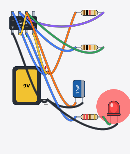
যা যা লাগবে · Parts you need
- 1 × 555 timer IC (NE555) 555 টাইমার IC (NE555)
- 1 × 9 V battery ৯ V ব্যাটারি
- 1 × Resistor 1000Ω Resistor
- 1 × Resistor 10000Ω Resistor
- 1 × Capacitor Capacitor
- 1 × Resistor 220Ω Resistor
- 1 × LED (red) LED বাতি
- 13 × Jumper wires জাম্পার তার
তার লাগানো · Wiring
| 9 V battery + | → | 555 timer IC (NE555) VCC |
| 9 V battery - | → | 555 timer IC (NE555) GND |
| 9 V battery + | → | 555 timer IC (NE555) RESET |
| 9 V battery + | → | Resistor a |
| Resistor b | → | 555 timer IC (NE555) DIS |
| 555 timer IC (NE555) DIS | → | Resistor a |
| Resistor b | → | 555 timer IC (NE555) THR |
| 555 timer IC (NE555) THR | → | 555 timer IC (NE555) TRIG |
| 555 timer IC (NE555) THR | → | Capacitor + |
| Capacitor - | → | 9 V battery - |
| 555 timer IC (NE555) OUT | → | Resistor a |
| Resistor b | → | LED A |
| LED K | → | 9 V battery - |
Code (Arduino C++)
// No Arduino here! The 555 charges the capacitor through R1 + R2 and empties it
// through R2 only, flipping its OUT pin all by itself between 1/3 and 2/3 of the supply.
// Blink rate = 1.44 / ((R1 + 2 x R2) x C) = 1.44 / (21k x 10uF) = about 7 blinks per second.
// Try it in the simulator: change R2 to 47k and watch the blink slow down.
// R1 = 1k, R2 = 10k, C = 10 uF, LED through 220 ohm on pin 3 (OUT).
আরো project · More projects
- ৭৪HC595 শিফট রেজিস্টার দিয়ে LED চেজার (৮টা LED, ৩ pin)LED chaser with a 74HC595 shift register (8 LEDs, 3 pins)
- হার্টবিট মনিটর (MAX30102 + OLED)Heartbeat monitor (MAX30102 + OLED)
- ESP32 আবহাওয়া স্টেশন (BME280 + OLED)ESP32 weather station (BME280 + OLED)
- হোম অটোমেশন: ব্লুটুথে ৪টা বাতি (রিলে মডিউল)Home automation: 4 lamps over Bluetooth (relay module)